


smiffy
-
Posts
86 -
Joined
-
Last visited
-
Days Won
2
Content Type
Profiles
Forums
Gallery
Blogs
Events
Articles
Store
Downloads
Everything posted by smiffy
-
This dates from 1944 .contract no 294 /S5134/con23A and 294/23/S2178/con23A for the 3ton 4x4 load carring chassis and contract 294/23/S3035 /con 23A for the4x4 tractor chassis. My IGL 3 chassis is 1937 and Engine no 31777
-
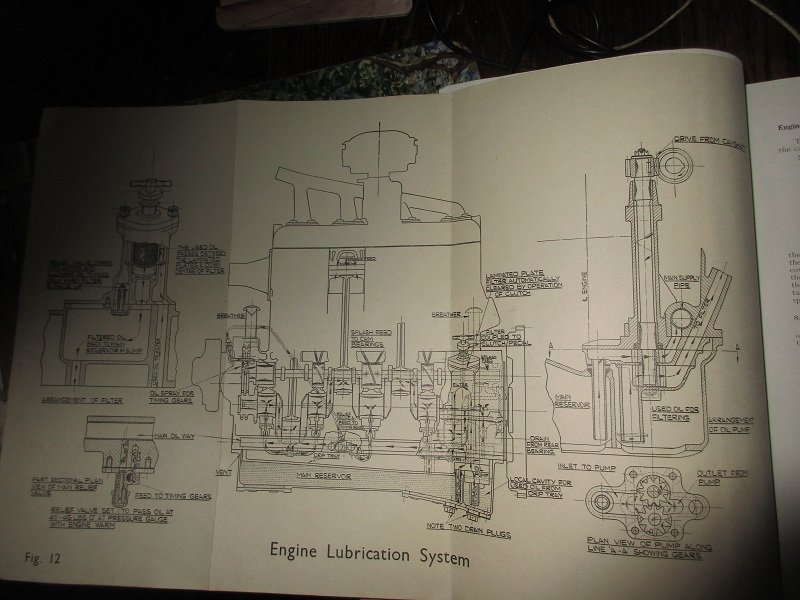
Engine Lubrication chart
-
There is no separate oil tank .the sump is in 2 sections with a scavenger pump transferring the oil to the second section from where it is pumped via the auto clean filter to the bearings . The carbon deposits removed by the auto clean fall into a separate section which is drained every 2000 miles via a plug at the base of the filter housing The auto clean filter is automatically cleaned every time the clutch pedal is depressed Mike
-
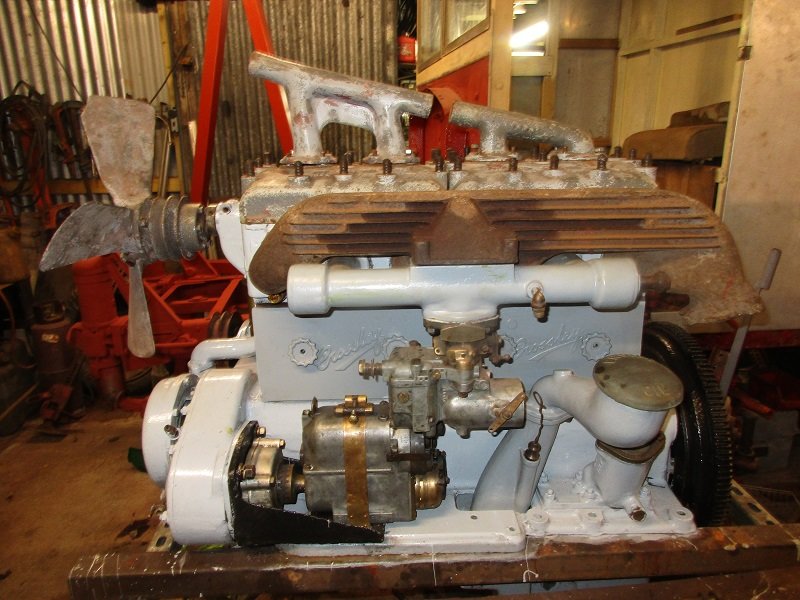
The FWD model was not built until 1940 and all models were fitted with a dry sump engine . Do you have a positive date of manufacture for yours ? and what is the engine no . The no is stamped into the crankcase above the front pulley on all the engines I have seen . The no of Crossleys that survive are few and far between so a rare beast and it looks in good order. Mike
-
The basic engine design remained unchanged from the I G L 3 to the end of production .Early engines have aluminium crankcases this was changed to cast iron due to a shortage of aluminium some time after 1940 . Early engine have a up draft carburettor and a simms magneto .The 90 hp engine has a down draft carburettor modified cylinder heads and a distributor driven via a right angle drive . The bracket remains the same on each engine and the mag or distributor are interchangeable .The sump is modified on the 4x4 to allow clearance for the front axle . Cylinder blocks are interchangeable across all models. . Mike
.JPG.18b5ec595cddc7af6f8aa31af7c1f15b.JPG)
-
Try this company http://amalcarb.co.uk/
-
Excellent work as usual . I dont know how you manage being so far away from the truck .My workshop is about 50 foot from my machine shop and I moan about how many times in a day that I walk between the 2. Mike
-
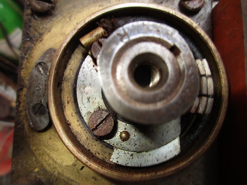
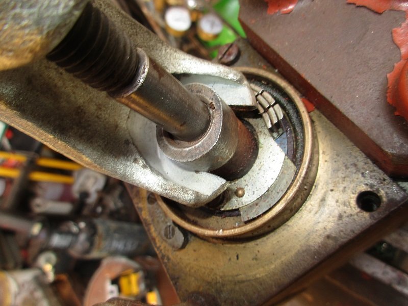
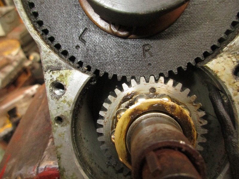
Simms SRM4 direction reversal Remove points cover and distributor cap Undo screw in middle of cam Make a small puller and remove cam ,note the letter stamp on the cam to indicate rotation direction Remove backing plate behind points Find the dot on the small gear which should line up with either the L or R mark om the distributor gear and set appropriately Replace cam in correct position remark direction on mag body so you dont forget that the arrow on the oil cap is now in the wrong direction


-
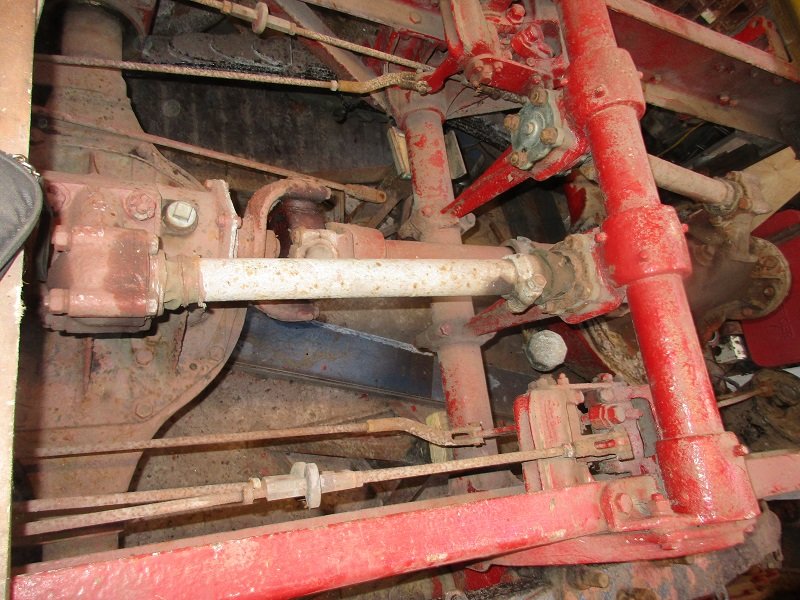
Yes mag is SRM 4. I think that I fitted new bearing ,but it was over 30 years ago. I do have a few spares in various states of repair .that I will repairing if the need arises. The mag was the wrong direction of rotation when I aquired it, so I reversed the direction . It has a good spark so will leave it alone. I stared getting the gear box into shape to refit fortunately its in fair order , When I started this restoration i 1985 I fitted new bearings and fitted lip seals in place of the original felt seals . The gearbox is a real sod to fit . as it has to be lifted up from underneath and is a very tight fit. . It also sits on a sub frame ,with a carden shaft to the clutch .It was obviously fitted before the cab . I cleared all the bits of the rear to start assessing what needs doing . When I started this project I did a huge amount of work on the axles and breaks etc Hopefully this is still ok but it will require a lot of work to get it to a good standard


-
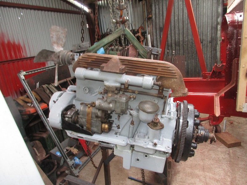
Fitted the engine today. It sits on a sub frame which is is mounted in plain bearing at the front , is ridge mounted in the middle and a spherical bearing at the rear. Once the engine is fitted it is very difficult to work on ., even changing the started motor or water pump is awkward .

-
I only need some tyres to get the truck mobile they would not be used on the road , so will try and get some casings .The new tyres will not be needed for some time yet. Mike
-
Thanks , I had seen these tyres but was hoping to find some part worn . When I last brought any tyres there seemed to be plenty around but that would not appear to be the case now . I will just have to bight the bullet and buy some . I have promised my better half an extension and new kitchen next year , she might not understand that tyres are more important than a new cooker Mike
-
My thoughts are turning towards getting the truck mobile as I need to turn it around soon . Can anyone point me in the right direction to obtain 900 x 20 bar grip tyres . The last time I required some was over 20 years ago and they were readily available but now it seems to be a different story. Mike
-
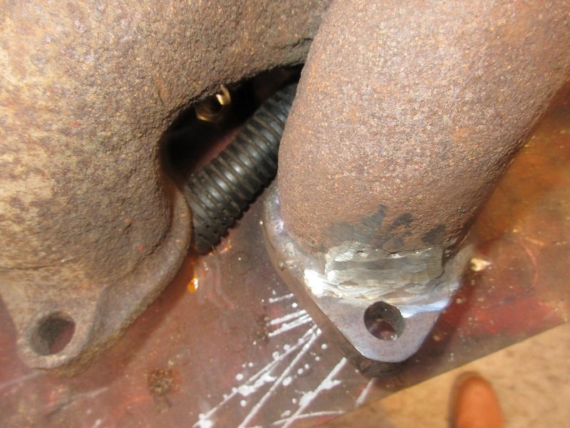
I have assembled most of the engine .having replace all the manifold stud etc . The exhaust manifold had one broken flange which I machined off flat and having cut a new flange I welded it on using a 29/9 rod

-
I am referring to the valve timing at tdc not the mag timing which will be set at a max of 30 degrees btdc
-
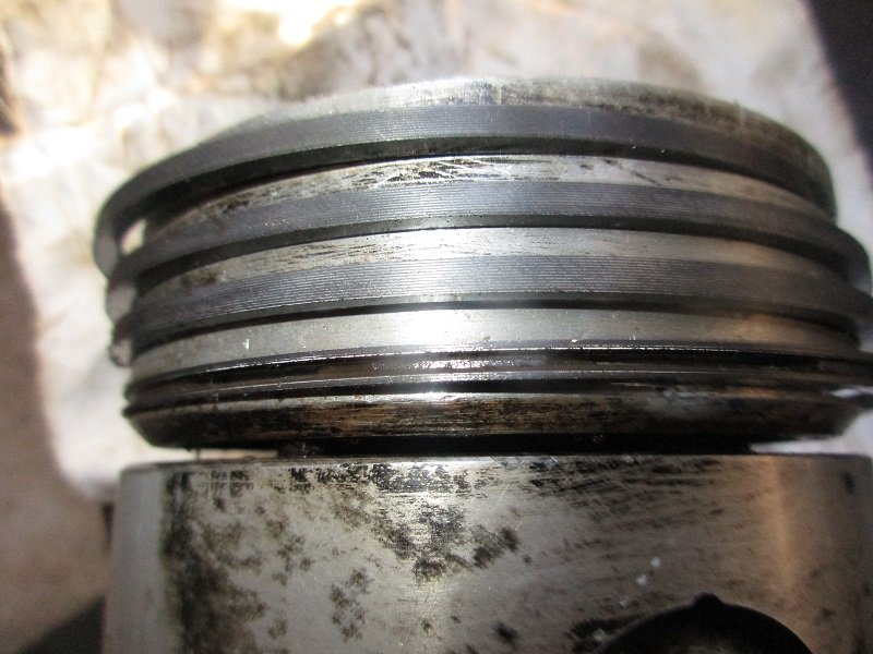
i will carry on rebuilding my original engine as i have enough parts . The pistons are of a rather odd design as they are machined right through below the oil control ring and the crown of the piston is only attached by 2 luggs cast up above the gudgeon pin. I have refitted the mag and auto advance . The drive chain adjustment is for camshaft and mag is by sliding the housing out and to lock it in place the mag support bracket is serrated and locked with serrate washes . I will set the timing with the piston at T D C and set the valves on the bounce, and hope this is about right


-
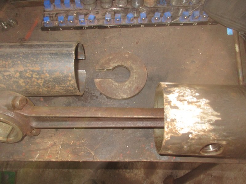
I stripped the new engine down and removed the pistons. I decided to remove the pistons out of the top of the blocks as this was the shortest distance and they were badly corroded in the bores ,so hand to make a horseshoe washer and pushing tube to enable me to push on the piston and not the conrod . Before attempting to remove the pistons I boiled the blocks in oil for several hours to try and get some lubrication past the pistons . This only had limited success and the pistons took considerable force to press out I have decided to use the parts to build a spare engine as I have a spare correct aluminium crankcase . The engine I stripped down has a cast iron crankcase The blocks will need boring out and fitting with egg shell liners and at the same time have valve seat inserts fitted as the valve seats are very badly pitted. By fitting egg shell liners I hope to be able to use the existing pistons and just fit new rings as i have had no luck trying to obtain new pistons


-
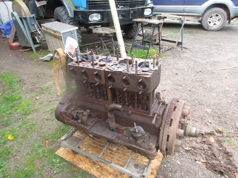
Last year I acquired a spare engine It is from a much later 4x4 truck but the blocks piston , con rods and crankshaft are the same. Today I made a start on stripping it down . It always amazes me that even when parts look completely rusted together how easily nuts and bolts can come undone . When I I try to do the same with modern nuts and bolts it usually ends having to resort to cutting them off .I can only assume that the steel used is of a different quality . Hope fully the con rods will be better than the ones in my other engine


-
I have not had any time to work on the Crossley for nearly a year but have built a new workshop for my other project so should have a bit more space . I now have most of the parts so should be able to start putting it all back together and started with the air springs I had ordered some new leather seals which I have fitted and they are now ready to be fitted back on the chassis . Hopefully I will get back on track over the next few months but must remember to stop getting involved with more new project Mike
-
Vernier couplings are available here https://www.vintagecarparts.co.uk/search?query=19%2F20+coupling Mike
-
Would the joint not have been originally spelter brazed . The spelter is first placed inside the tube ,the flange is fluxed with borax and pressed home ,the whole unit is placed in the forge and brought to heat and positioned so the spelter runs into the joint . Spelter is a equivalent of modern brazing rod but in pellet form This is how axle ends were fixed into tubular axles on many small cars including Frazer Nash Mike
-
What flux do you use ? I use Tenacity no 5 which seems to stand the higher temperatures and I would use oxy acetylene as the heat source . Is it possible to tig weld the propshaft . Mike
-
I would TIG weld thin aluminium as it is much more controllable than mig , I use gas diffuser nozzles and pre flow the gas to get a clean start and pure argon gas, .also a foot control pedal to control the amps is essential ..With some practice its possible to weld soft drink cans and aluminium kitchen foil If using a mig without a spool gun it is worth fitting a new liner as any wear or dirt in the liner will cause extra friction and balling at the feed rollers and use 1 mm wire
-
My early Jowett car is fitted with a similar oil level gauge . The wire from the float exits the crankcase via a piece of 3/8 bore steel tube which has a cap at the end . When the cap is removed and if the oil level is correct the float pushes the wire about 1.5 inches out of the end of the tube . I will have a look to see what details I have of the float. Mike
-
I only know what works for me . My other interest is clock making and I follow the procedures laid out by W J Gazeley ,Brittan and John Wilding in their books on clock making and repair.. I start with a broken main spring which for the main outer springs I cut to length and machine the slots . This can be done without annealing and retempering . The problem is with the springs that act onto the snail cams inside the unit .These have very tight bends in them . I had to anneal the spring or it snapped when bending . It is then too soft to act as a spring .I heat the spring to a bright red and quench in oil . I then polished them to a bright finish . and heat them until they become blue -purple and quench them in clean water.


.JPG.18b5ec595cddc7af6f8aa31af7c1f15b.JPG)


