


Cel
-
Posts
252 -
Joined
-
Last visited
-
Days Won
1
Content Type
Profiles
Forums
Gallery
Blogs
Events
Articles
Store
Downloads
Everything posted by Cel
-
It looks like a Cletrac, could be a very early one. There are some differences with this one: https://ww1photographs.wordpress.com/2013/04/21/cletrac-tractor-1917/
-

Robert Beaufils collection coming up for auction
Cel replied to Great War truck's topic in Pre WW2 vehicles
That is a very nice collection. Is this the Mack and Mathis that were found in Marseilles? I'd love to go but too many projects awaiting their turn and saving for another dream project. -
Many thanks for the replies! I would also say it is an oil cabinet for new oil, as there is no filter inside and it looks too clean for being used for waste oil. It can also be locked although I have no key. It will make a nice display and I can probably use it to store my SAE30 oil. Regards Marcel
-
Many thanks for the replies! You may well be right about that, although it can also be used as a parts washer I think. There is some sort of valve that closes the sieve drain when you close the lid, that made me think it is a parts washer (to prevent the volatile part of the liquid from evaporating), however the tank is very clean on the inside and can be locked so that makes it more likely that it has been used to store fresh oil I also tried looking up the patent but no success. So late Victorian would mean pre-WW1 if I am not mistaken? Thanks, I went looking in the very same street as well, I find it fascinating that a lot of manufacturers were located in small workshops. Sadly the remains of these places are disappearing at a fast rate. That is absolutely true, it was a different world. I found this tank hidden in a collection when checking out a stationary steam engine. This engine comes out of a tannery that was demolished in the mid 70s to make way for Brussels airport. I ended up buying both items, the price/weight ratio of the tank being definitely higher than for the engine😝
-
Not sure if this parts washer was used in WW1 but it could be possible? Anyone has ever seen one like it? Gustav Richter's patent of the Richter Manufacturing Co in Bradford. Regards Marcel


-
You could also use a drilling head clamped to the valve stem. With a drill or manually, depending on the amount of material that has to be ground away. Pressure can still be applied from the other side if needed. I did the same with a 1940's Bentley engine a few weeks ago, your valves should be easier as there is no groove for the collets. I am sure they will come out nice though!
-
That would make the 3rd one known in existence, any chance you can post a picture here? I have found some documentation, it looks like these trucks have been used for quite a long time after production came to a stop in about 1932-34. Not many Dewald trucks were in military service, despite their efforts.


-
I would still go with a welded pipe. Instead of a bolt to act as a puller maybe a sledgehammer. The impact should make a big difference. I tried the same with a gib key and made a puller because I didn't want to damage the key. No result so I welded a bolt to the key and with a homemade sledgehammer it was only a matter of seconds.

-
ww1 Holt Tractor and French Tractor glass photos
Cel replied to Morris C8's topic in Pre WW2 vehicles
Found the picture, had it saved some years ago from another forum I guess. A 30-60 Rumely E in Ukraine in 1916.
-
ww1 Holt Tractor and French Tractor glass photos
Cel replied to Morris C8's topic in Pre WW2 vehicles
There is a Holt 45 in the Netherlands that was found in France. For those interested in the restauration of the Big 4 this thread is an excellent reading: https://www.smokstak.com/forum/threads/gas-traction-big-4-from-blomgren-estate.81774/page-62 -
ww1 Holt Tractor and French Tractor glass photos
Cel replied to Morris C8's topic in Pre WW2 vehicles
That is right, although I don't think it was found in France. There seem to have been a number of prairie tractors gone to Russia during WW1, I know I have seen a picture somewhere of a Rumely towing a large gun. -
ww1 Holt Tractor and French Tractor glass photos
Cel replied to Morris C8's topic in Pre WW2 vehicles
I would say they are American 'Big Four' tractors. https://monthly.mecum.com/2019/09/28/the-big-four/ Quite interesting that these prairie tractors were in France, I wonder what happened to them. -
It looks like the inner race is accessible enough to weld a bushing on with a hole with fine thread at one side, a bit like a puller. That way you apply the force directly to the stuck part. Good welding skills are required, and basic electrodes would be my preferred choice. Good luck! Marcel
-
The 1525 should have the KM engine, basically the same as the IM as in my 1504 only a bit more displacement. Here is a picture of the fan setup, it is an eccentric axle that is also a tensioner for the flat belt. Not sure what you mean with oil pump plunger, but these engines have a gear pump that fills the gallery for the main bearings lubrication and the channels in the sump for the conrod dippers. No dipstick but a cork float with a stick coming out and a contact to stop the engine in case of low oil level. Regards Marcel


.thumb.JPG.fb5b8d5c4792d79071fb73c8d22ec232.JPG)
-
Many thanks, I presume that is because of the radiator fan? Until now I have not come across a picture of the same engine. It looks fairly big for a car although not impossible but I like the tank idea! There is some kind of gear wheel installed behind the clutch, what could this be used for?

-
I found this Th. Schneider engine, it is a fairly big engine.. Anyone an idea what these engines were fitted in? Thanks, Marcel


-
When I was restoring the Peugeot, a friend who has several old cars and motorcycles recommended Rhino Silkolene 140. He has used this oil for several decades in his vehicles, so that is what I am using.
-
Making gears is a lot of fun! I have spent a few days figuring out the maths before attempting to make these on my contemporary milling machine. They were missing from a 1912 gas engine that I am restoring. Looking forward to seeing the new gears, it would be nice if you could make some pictures of the machining. Marcel


-
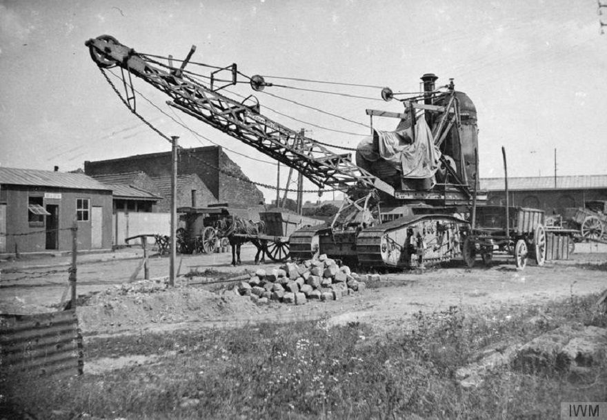
I found the picture of the big crane. I am almost sure that I saved it from this forum but I don't know who posted it first. Regards Marcel
-
I would love to restore one of these. Were they actually used during WW1? I remember seeing a picture of a crane on a tank chassis, I think it was on this forum. Here is a picture of a Dewald with a crane mounted, post WW1. Regards Marcel

-
Those rear hubs remind me of the hubs on the Renault HO tractor, I don't think it is electric driven. Anyway, it is a fantastic machine, I want it 🤪😀!
-
The torque on the diff and the halfshafts is higher on a worm drive rear and than on a chain drive. I think that is the reason that chain drive was used on quite a few heavy duty trucks until the 1950's.
-
M16 Halftrack restoration/build. A long long road.
Cel replied to Chris Hall's topic in Tracked vehicles
I think this yours as well, pictures taken back in 2012. There were lots of interesting things there but back then nearly impossible to buy anything. Quite a few people must have watched the site as I know of several items that found a good home after the owner passed away.


-
I was given these wheels. The rubber is held onto the rims with a steel band in the center. Outside diameter is about 730mm and width 100mm. The centers have been cut out many years ago. Anyone recognize from what vehicle they might be? Regards Marcel


-
The water got into the sump, we drained it off when we got it home. The engine is loose but will need complete dismantling before we will attempt to start it again. Transmission was just above the water level, and as it is a chain drive the diff is integrated into the gearbox so no rear end issues. Marcel


.JPG.cf54148935f4429aed34402f3144973b.JPG)


