


QL Driver
-
Posts
62 -
Joined
-
Last visited
-
Days Won
1
Content Type
Profiles
Forums
Gallery
Blogs
Events
Articles
Store
Downloads
Everything posted by QL Driver
-
Couldn’t it have been forged in two or more pieces and forge or electric arc welded?
-
Ben - looks like another interesting project! The JAC mark has been touched on here before. On our Garrett wagon there are a lot of steel castings marked “JAC”, and they are believed to have been cast by Catton’s foundry in Leeds.
-
It’s a Scammell tractor.
-
Steve, I don’t have the details on the engine, I’m afraid! The radiator is indeed new. I’ve not seen the Knox in person yet. The thing I was struck by from the photos (and by Dad’s description) is that it’s enormous. The top of the radiator is about 6’ off the ground!
-
Hi Everyone - I thought there might be some interest in these updated photos taken this weekend. As you can see, there's a great deal of progress! I don't have any specific technical updates... but as ever, any new info, parts, drawings, photos, etc would be of interest!


-
Not uncommon. Our Garrett wagon is the same.

-
Could always go and get some white lead, Tomo! Call it a "work of art"!
-
If the piece in the middle of the photo was laid on its back (same orientation as the piece on the right) for ramming up, then it will leave the core print exposed at the bottom. The core goes in, then leaving a space behind for the part, and the other half of the mould is just flat sand. Right?
-
WW1 era Commer chassis on eBay: https://www.ebay.co.uk/itm/292237556049 Looks like a good potential starting point for a project!
-
We steamed the rail around the front of the Garrett cab roof, which is about an inch thick. A big piece of plywood with some blocks on it as the 'mould', and a couple of hours in a piece of old flexible chimney liner with the end stuffed with rags, with steam from the boiler in at the other end, and it worked fine.
-
Yes, although these were white metal. https://www.artisanfoundry.co.uk/product_info.php?products_id=205 We are fortunate that we know what all of the casting marks should be, so we try to put them on when possible.
-
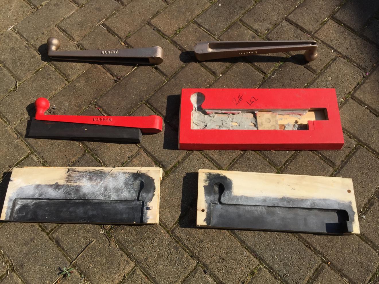
Steve, have you considered making an oddside? I was inspired by your threads on here to make some patterns for the Garrett. I made one handle (a smaller one than this) as a split pattern, but then I was told about an oddside (the part in the middle row, on the right). The idea is that rather than making a split in the part itself, the oddside defines the split; the first half of the mould is rammed up against the pattern, with the pattern in the oddside, and then the oddside is removed for ramming up the second half. The way we made it was to trace the outline of the part onto a piece of plywood, and then cut out with a coping saw. The back was then filled in to make it sturdy enough for ramming up. It only took a couple of hours to make, and it should make the mouldmaking process easier (and perhaps cheaper?).
-
Don't forget that leaded petrol is too modern for the Thornycroft...!
-
Whilst it's not cheap, there are commercial printing services; e.g. http://www.shapeways.com. You upload the model, they print it in your chosen material and post you the part. I used this to make a pattern for a works plate for the Garrett trailer to go with our wagon. The pattern cost something in the range of £15, I think!
-
When I was discussing this yesterday with the owner, one of the remaining questions to be solved is the hydraulic pump for the rear brakes. Apparently it should have a hand lever operated pump to actuate the brakes on the rear axle. As ever, any leads on Knox parts would be appreciated!
-
So, here's the state of play... A lot has been worked out, and various other components have turned up at Keeley's since the sale. It turns out that the components included in the sale appear to all be Knox (or Maudslay). There are various leads being tracked down to get things together. There's apparently a 1915-ish Knox catalogue out there that from the images available, appears it would clarify some of the details... so that's an item being looked for at the moment. I hope this is of interest!

-
There is indeed substantial progress... I need to speak to the owner to see what I can share.
-
Yes, it's similar to the "unfortunate" impossibility of buying asbestos for insulation and valve packings!
-
Wouldn't a fracture due to cold forging happen at the time of hot working the material, rather than after cooling (note Steve's description of breaking it when trying to tweak it in the press)? A cold fracture suggests some undesirable metallurgical transformation.
-
Tim Interesting thoughts. To be honest I've got very little information on the Maudslay side of the equation, but my supposition is that as the vehicle was used as a yard crane, the idea of it being heavily geared down by running through two gearboxes (the Maudsley box followed by the prop shaft to the Knox box) wouldn't be problematic, and to get the power take off for the winch to work, the Knox box would have to still be driven. Based on the cab design it bears a strong resemblance to a 1930-ish Maudslay 5 ton wagon. I found a photo of one via Google where it was fitted with pneumatics and had the cut outs in the cab floor for the wheel arches but haven't been able to find it again. [edit] this isn't the picture but shows the general design: http://www.stilltimecollection.co.uk/detail/29412-tpt-transport-truck-lorry-wagon-maudslay.html Ed
-
So, per Robert's request above, here are the Knox components separated out. Unfortunately I don't have any photos showing the Maudslay side of the pile. Does anyone know where the Matador in the sale went? I've been told there were some Matador parts included in this lot, and so it's suspected some Knox/Maudslay stuff may have gone the other way. The owners would like to rectify that error! Rear Axle and Radius Rods This is the original rear cross member. Drawbar eye and original rear cross member. The chassis and gearbox together. Not the brake drums/hubs in the background. Gearbox internals Number stamped on the brake gear.
.JPG.4f3a572329ef6ab56515581c8f82ea83.JPG)
.JPG.d9e00ab14e68cc48282ff2348e53b02a.JPG)
.JPG.729bb89db238722bef0c432a5ef4fec1.JPG)
.jpg.e6232f2071f9b74d922e560fc2ee8183.jpg)
.JPG.9b85ede0a9683583fb4baabc1f468d24.JPG)
.JPG.7efe4ad0e73a64a20ce20d7dc6792ca4.JPG)
-
I also managed to track down the March 1915 copy of Motor Age, via the University of Michigan Library: https://babel.hathitrust.org/cgi/pt?id=mdp.39015080122008;view=1up;seq=42;skin=mobile The link above gives a clearer version of the line drawing of the side of the tractor.
-
Tim - thanks for that lead! I tracked down the "Motor Truck Design & Construction" book that the chassis drawing came from: https://archive.org/stream/motortruckdesign00scharich#page/217/mode/1up I suspect there's useful information in there for anyone restoring American trucks of the era. Based on the evidence at hand, it's quite convincingly a Model 36 rather than Model 35. The 35 was the artic tractor with the separately sprung fifth wheel and chassis, and the Model 36 was a direct haulage tractor. Fortunately the front end that's missing is identical between the two types. I also found large volumes of information on Google Books. Unfortunately in the UK they aren't accessible without some tricks (http://www.strangehistory.net/2014/06/08/problems-accessing-google-books-outside-us/), but there are lots of contemporary journals that have been scanned and I found several technical descriptions of the Knox tractors.
-
Tim - you're correct, it is the Knox part of the Knox/Maudsley yard crane from Keeley's (the idea being to split it back into its constituent vehicles). There is another 3 wheeled Knox tractor at the San Jose Fire Museum - http://www.sjfiremuseum.org/portfolio/1914-knox-martin/ It appears those two are the only complete ones - and the one at the Smithsonian is no longer on display. Thanks for the lead on the Wheels & Tracks issue - I'll pass that on!
-
Hi all, A friend of mine has recently acquired some substantial parts of what's believed to be a c.1915 4 wheeled Knox-Martin tractor and he would like to restore it. Its history is unclear, so we're unsure of whether it saw military service, but it's of the type used for the tank transporters. Information on the Knox seems to be fairly thin on the ground. Does anyone have any leads on technical information, drawings, or parts for a Knox? Thanks, Ed For those unfamiliar with the vehicle, this is essentially what it should look like:


.JPG.4f3a572329ef6ab56515581c8f82ea83.JPG)
.JPG.d9e00ab14e68cc48282ff2348e53b02a.JPG)
.JPG.729bb89db238722bef0c432a5ef4fec1.JPG)
.jpg.e6232f2071f9b74d922e560fc2ee8183.jpg)
.JPG.9b85ede0a9683583fb4baabc1f468d24.JPG)
.JPG.7efe4ad0e73a64a20ce20d7dc6792ca4.JPG)