


flandersflyer
-
Posts
264 -
Joined
-
Last visited
-
Days Won
1
Content Type
Profiles
Forums
Gallery
Blogs
Events
Articles
Store
Downloads
Posts posted by flandersflyer
-
-
It is certainly not a flimsy component. Even if there was some deflection in the work piece the diameter of the arm between the taper and the socket is not critical.
It was a mildly sexist comment I were making
☺😯☺
-
The glamorous assistant required some entertaining and dining this weekend but helped out in the garage for the rest of the weekend.
I started on the replacement steering arm by facing and centre drilling a length of EN3 steel.
[ATTACH=CONFIG]112941[/ATTACH]
Then turned the taper and thread on the end and checked it fitted the axle.
[ATTACH=CONFIG]112942[/ATTACH]
Using a bent piece of welding rod to work out the approximate length required
[ATTACH=CONFIG]112943[/ATTACH]
Then Sarah turned the diameter down for me.
[ATTACH=CONFIG]112944[/ATTACH]
It needs a keyway adding to the taper before heating up and bending. Then it will need cutting off to length and a boss shaping for the ball joint to fit to. I need to machine a tapered socket for the ball joint and that is probably beyond the capabilities of my facilities.
nice to see a rollorbox wasn`t involved
-
I am making this up as I go along but for the rear brace I plan to drill through the vertical faces of the casting and bolt through to the braces this way.
The front pair will be much more of a challenge. There is a reasonable amount of the nearside mount remaining but the offside one is completely missing. This will probably involve fabricating a copy of the missing mounting, then trying to weld it to the existing casing. For this brace I think I will resort to bolts through the case to the inside of the gearbox as well (making sure I position them to miss the gears).
run some solder across the whole of the contact area
theres enough cross sectional area available here to stiffen it all up...
-
One of the nice things about Ben's new house is that there is scope for lineshafting.
I wonder if anyone ever made a food blender for overhead belt drive?
my latest acquisition:

-
I`v got a Lister SR1 with quite a bit of discolouration on the bore
it also had a broken ring....and there was a bit of rough where the gudgeon pin was....(sat in a farmers field for 20 odd years)
I just wiped it all out by hand with some 1000 grade & oil in a crosshatch pattern
discolouration is still there and there`s a bit of pitting where the rough was
but it'll live to fight another day
its all about how you feel it'll cope.....then just go with it...
-
MAPP gas will braize that....
-
I brought it home on a tandem trailer behind my trusty 1956 ‘FJ’ Holden. That is something you could not do today, 3.75 tons behind a car weighing just over 1 ton. Petrol at Rosedale was 64cents a GALLON. ($0.14.2 cents a litre)
[ATTACH=CONFIG]113210[/ATTACH]
The chassis stripped down for straightening and sand blasting. The tyres were pretty sad.
[ATTACH=CONFIG]113211[/ATTACH]
The engine was seized and I left it for 6 months with the chassis jacked up on one of the flywheel bolts. Diesel was pored into the cylinders each week and one day the chassis was sitting back level as the seized engine had turned over.
[ATTACH=CONFIG]113208[/ATTACH]
[ATTACH=CONFIG]113209[/ATTACH]
More to come
fantastic!!
don't you just love it...
-
may be of interest to Steve
http://www.ebay.co.uk/sch/hootflipflopandfly/m.html?item=252402495424&rt=nc&_trksid=p2047675.l2562
local to him as well (Leicester)
-
Well, yes and no. I'd agree 11 out of 10 for making it, but if you have a look at the original casting it's clear that the radii were never perfect and the edges were never square. The original casting looks to have been spot-faced to a different depth on each side, and you can see the centre hole wasn't really drilled exactly in the centre. This new part is just a bit too good.
The crew have put a huge amount of time and effort into this truck ( I think Dennis was up and running about page 100, Thor is now at page 215 ... ) and clearly have decided to leave original pitted surfaces on many components rather than go for perfect factory finishes.
The down side is that a perfectly produced well finished new component is just that bit more obvious. Of course you could just throw it in a cement mixer with a bunch of steel scrap for an hour or two, then leave it outside in vinegar for a month, followed by a heavy grit blast, but the balance between new and old has to be managed by the restorers that are actually doing the job.
Any comments on your logic for showing / hiding component age, chaps?
Any idea if the radiator end stay rod mount is the same / similar?
but it demonstrates the demise....and subsequent resurrection of the vehicle....does it not
I think it OK to manufacture and use new looking components...where needed.
To artificially `age` something in order to `blend in` would be fakery...
just a thought mind you...
-
OK
Nice work your doing ben
-
[ATTACH=CONFIG]113248[/ATTACH]
I like houses that have 3 Phase Electricity!
How are you getting the 3 phase?
is it coming in from the DNO or are you artificially creating L2 & L3 with capacitors?
-
Just wanted to say to the Devon team to keep at it....definite progress being made and great to see
I`m currently on with a few projects of my own...nothing military...just some Petter & Lister diesels that I`m restoring
I may start a thread on em in non-topics
-
I've had a hard time getting media-blasting businesses to return my calls but I'm open to the idea, especially if I decide to fully strip the interior.
Doing it myself would be a challenge since a had a neighbor call the cops on me when I just washed the vehicle outside my shop. (worried about radioactivity, yes it was in the wrong conflicts and even then the 20 years since it was in service... but you can't argue with crazy) I suppose I could set up an indoor space but it's *awfully* messy.
Stay tuned as I plan to try some more expensive strippers for a better outcome.

my old granddad once told me theres much to be said about garden fences:
"they say nowt, mind their own business and get on with what their supposed to be doing"
theres much to be said for a good fence.
-
I don't think that it would need to be carbide.
I have used ordinary HSS Rotabroach cutters for birds-mouthing thick-walled tubes, so I am pretty sure that one woud have worked here.
With that job to do I would have relished the opportunity to realise a long-held ambition to own a mag-base drill.
But, failing that, with the guide plate I am sure that a Rotabroach cutter held in a normal drill would have worked.
If there is any likelyhood that you will be wanting to drill in-situ holes in chassis frames on an ongoing basis then I would strongly suggest keeping an eye out for a nice little mag-base drill.
yep.
plenty of water on it during cutting...at a slow, steady speed with a steady pressure applied during cutting
L. S. STARRETT make what I consider to be the best holesaws....I use em regularly to cut out holes for downlights (I`m an electrical contractor)
DART are good n all..
-
Thanks Chaps. I shall invest in some bronze and tighten it up a bit. It does feel a bit generous at the moment!
Today we wanted to get the engine properly fixed down. Dad did not cut the bolt holes in the engine mounting angles when he made them as he felt it would be easier to mark them out from the crank case itself. He is right in this but I really didn't fancy lifting the engine again. Still, I gritted my teeth and off we went. First job was to get the engine into line with the gearbox. To facilitate this, I made a pointer from steel strip to bolt to the gearbox input spider. This worked well and it was quite easy by adjusting the engine position with a jemmy to bring it all into line.
[ATTACH=CONFIG]111362[/ATTACH]
[ATTACH=CONFIG]111363[/ATTACH]
Then we had to lift the engine and remove the first mounting angle. All went well but I hate working under suspended loads. You only get one chance to get it right!
[ATTACH=CONFIG]111364[/ATTACH]
We put the holes in using the mill. As usual in this game, the mill was stretched to capacity, firstly by height in drilling a 1/2" hole and then in torque turning a 3/4" end mill to finish.
[ATTACH=CONFIG]111365[/ATTACH]
This was done for both sides and then, much to our relief, the engine was lowered back down.
[ATTACH=CONFIG]111366[/ATTACH]
We had four bolts in stock which were trimmed to length and had split pin holes drilled before fitting and tightening up. They went through all of the holes without adjustment!
[ATTACH=CONFIG]111367[/ATTACH]
The engine is now installed!
[ATTACH=CONFIG]111368[/ATTACH]
Gearbox to be finally fitted tomorrow along with some other bits and pieces which can now go on. One thing is bugging us though. Some time ago, Father repaired the rear wheel tyre size plates and I made up some brass screws to secure them and these can now be fitted. However, we cannot find them! Dad has been searching all day and it is causing serious annoyance!
More tomorrow.
Steve
this is where a MAG drill/rotabroach would have been better Steve
-
I made the king pins from EN24T as this can be nitride case hardened and this process should not change dimensions. EN24T is a really tough steel so well suited to this application but I struggle to achieve really close tolerances and a good surface finish when using it. For smaller components I have often left them very slightly over sized and then polished them back to size with some wet and dry (SiC) paper.
For the king pins I want a reasonable interference fit in the axle beam but for the pin to be around 0.001" smaller at the top so it starts off as slight clearance fit. It would have been quite a large surface area to polish back but I have access to a Jones and Shipman cylindrical grinder at work. Despite being over 60 years old this machine is still a pleasure to use; it is easy to achieve a very slight taper, can work to tight tolerances and leaves you with a mirror finish.
[ATTACH=CONFIG]110657[/ATTACH]
After grinding I wrapped some wet and dry paper around a pen and used it to polish out any sharp edges on the oil grooves. Once this was completed they looked like this and I was able to drop them off for a 90 hour nitride cycle to give a case depth of around 0.028".
[ATTACH=CONFIG]110658[/ATTACH]
place i once worked at had Churchill cylindrical grinders ..with a few Lumbsden surface flashers and a Prince crank grinder..
getting on but all good machines
-
I bent mine in the oven, as suggested.
I put them in the oven on top of a former, then took them out and pushed them onto the former with a tea-towel.
However, if I was doing it again I would not heat the former, as it took a long and uncomfortable time for things to cool enough to take the set. I think hot material onto a cold shoe would be better.
You can always have a second attempt.
i suppose steaming them into the correct radius..(a bit like they used to do to get Lincrusta round corners) would do it..
-
That would have been a better way to do it but they are just too big for my facilities. I spun the fuel tank ends for the Dennis which are 16" diameter and 18swg and that was quite successful although I had to make up a bronze tool to do it. They were at the limit of diameter for our Colchester Student lathe though and these covers are 22" diameter so although only 20swg, I couldn't do them that way. I could have imposed on my friends again for use of a larger lathe but am keen not to become a perishing nuisance!
I originally planned to solder the brass to the steel but felt that with dissimilar metals their relative expansions would distort the covers. I cleaned them before riveting so I could still do it. Will give it some more thought.
Steve
this wont be the problem
Electrolytic corrosion may well be though...in time...
-
Dear readers,
I was not quite sure where to post this, as one could consider it German/British/armour related. But I wanted to share this, as in my opinion it shows in its own way, how the German Imperial Army dealt with the introduction of the tanks by the British in WWI.
I do not know, when or where this picture was taken. I found it among others in a stash of photographs depicting the wartime experience of an enlisted man (Ersatzreservist), who served with 368th Regiment of infantry (10. Ersatzdivision) in France from around 1914 until late 1916 and subsequently with 429th IR (224. Division) in the eastern theatre of operations. 224. Div. was moved to France in September 1918. My guess would be, that the picture was taken in France, as tank warfare at the eastern front was limited.
Futhermore I think, that the reproduktion was build for training purposes, or just to give the men an impression of what they might have to face.
[ATTACH=CONFIG]108838[/ATTACH]
There is a caption on the rear: „Das neue feindl(iche) Angriffsmittel „Der Tank“ umstehend eine Nachbildung aus Holz.“
(German: The new enemy means of attack (or advance) "The Tank" overleaf a wooden reproduktion).
[ATTACH=CONFIG]108839[/ATTACH]
I hope, that this is of interest for you and would be pleased to read your opinions.
Kind regards
Gradez
it could have been used for Artillery recognition (a silhouette)..
or for flyers..
-
-
Thanks for all the useful input on piston ring gaps. Looks like they are OK, so we are getting closer to putting the engine back together.
I started the week by taking a piece of cast iron bar and turning the bore and OD to suit the gudgeon pin retaining groove. Then parting it off.
[ATTACH=CONFIG]108038[/ATTACH]
Then it just needed deburring and splitting with a hacksaw and it was ready to fit to the piston.
[ATTACH=CONFIG]108039[/ATTACH]
My next batch of laser cutting has arrived so I tacked a few of the bits together for the gear selector gate/handbrake arrangement, turned a boss and welded that on. There is still some work to get the exact arrangement sorted and the remaining parts laser cut.
[ATTACH=CONFIG]108040[/ATTACH]
how was the original boss fitted?
-
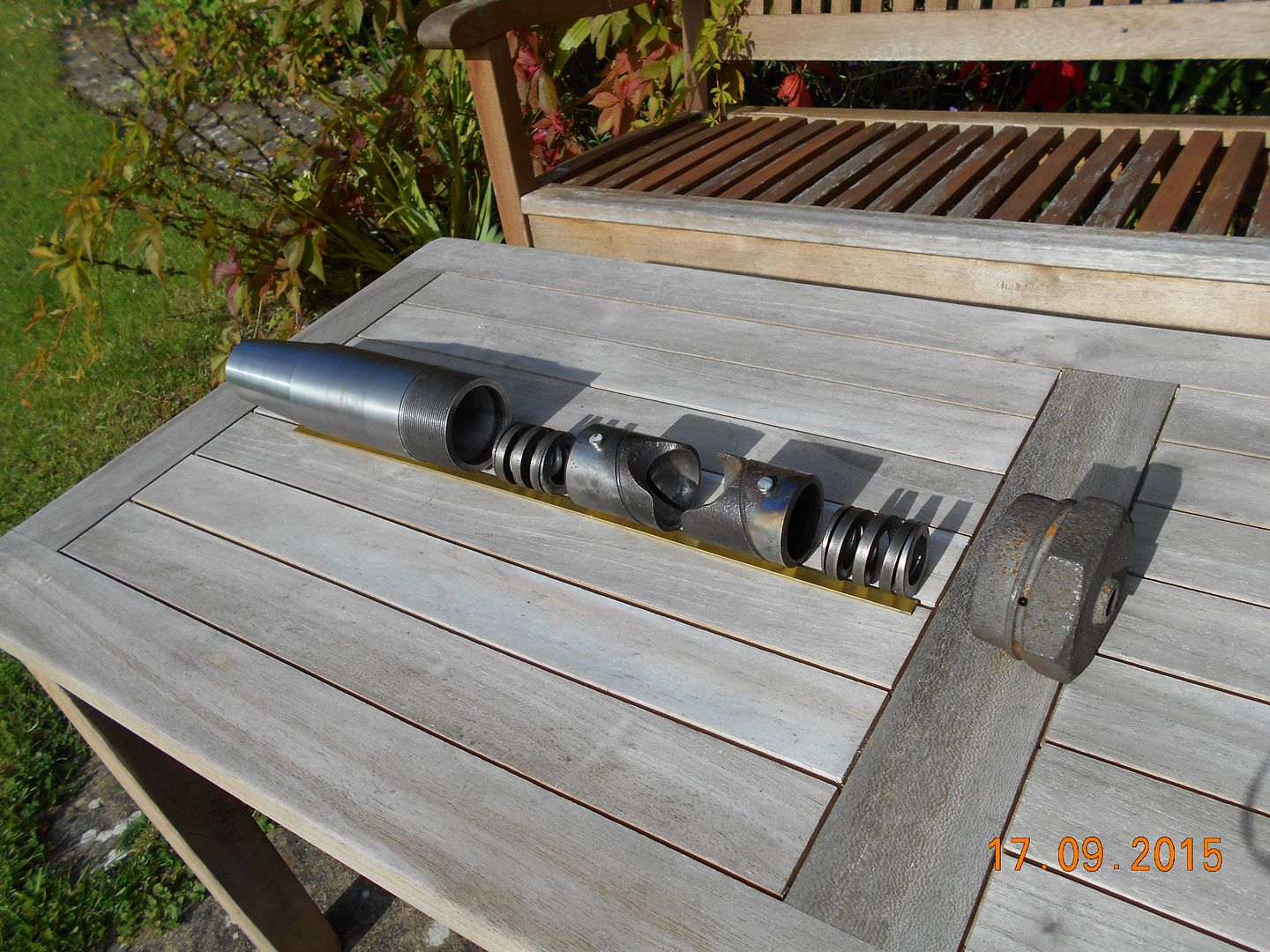
This pictures shows the “innards” that were recovered from the old sleeve and which can be used again – two springs and the two sliding sockets which encapsulate the ball.
what gets me is the amount of intricate work involved to manufacture these machines...
not really appropriate to war production is it
(i know they will have used jigs & turrets/capstans etc)...but...
-
If you are not set on using period technology then I think that 3D printing could be useful here.
Actually doing the texture is a bit tricky (computationally expensive) but I can imagine 3D-printing the lettering with a support structure then pressing that into a wax texture.
Of course, you would need a 3D CAD model of the plate, something a little bit like this:
[ATTACH=CONFIG]108133[/ATTACH]
or he could just do what i`v said at #47:
http://www.anaglypta.co.uk/our-papers/brand/original
rather than go down expensive and time consuming guff...
-
Not sure hardboard was around then, bit would give a textured effect if used
they may have used a bit of lincrusta.....

1908 Dennis Truck
in Pre WW2 vehicles
Posted
There were a chekko lathe recently on eBay ...I nearly bought it
That were down Norfolk
I don't think it sold
I've also got that small drills big brother...I'll bung a pic or three in when I get time