


.png.13c2ec34f1c53365a25f5885333b02b8.png)
johann morris
-
Posts
602 -
Joined
-
Last visited
-
Days Won
33
Content Type
Profiles
Forums
Gallery
Blogs
Events
Articles
Store
Downloads
Everything posted by johann morris
-
Thanks Lowfat, I have just ordered a bottle, it sounds just what i am looking for for all the electrical gremlins that i encounter at work. I have also got some of that red electrical varnish to coat the rest of the electrics inside the unit but it was the contact area that really concerned me. I found this interesting article on the product, from a BMW manual. Model:All BMWComplaint:Connectors which carry low current are more likely to form deposits which affect the resistance of the circuit through the plug connector. Depending upon the particular circuit these deposits can cause malfunctions and consequently activate warning lamps and check control indicators.Remedy:Part replacement can temporarily stop the problem.If the connector is the problem then without disconnecting the connector measure the resistance of the circuit running through the connector to make sure the connector has a high resistance. A good resistor will have close to 0 ohms resistance.Visually examine the male and female terminals in the connector housing by removing them. Look at the integrity of the wire crimps, and in some male terminals the integrity of the weld of the male pin to the terminal. Then reinstall.With a zero residue electrical contact cleaner liberally spray the male and female connectors, and allow the air to dry.Apply Stabilant 22A to both male and female terminals so they are saturated, and reconnect the connectors while they are still wet. When the Stabilant 22A dries it will leave a thin coating of polymer film which is conductive between mating surfaces, and is non-conductive between adjacent pins. It can also prevent the formation of more harmful deposits. Thanks for all the advice that you have all given it is much appreciated. Jon
-
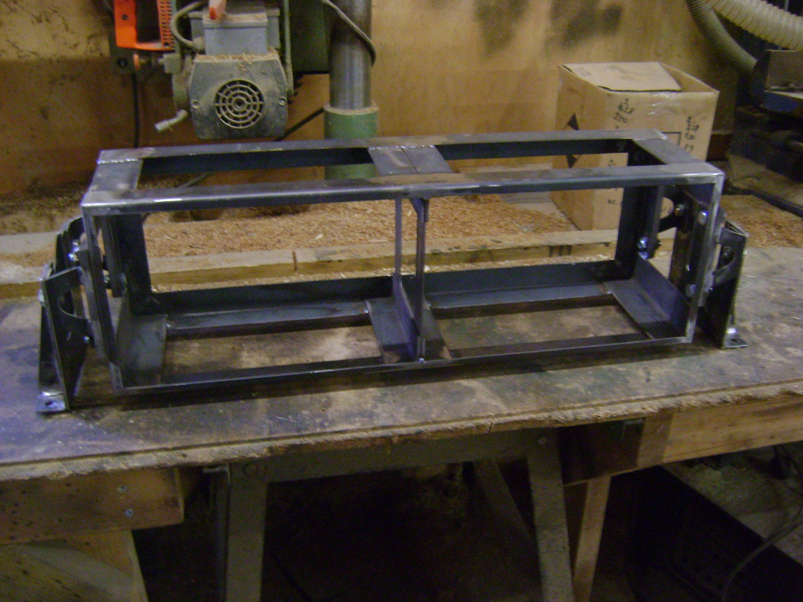
An interesting idea John but i think that it would be safer for all the other road users if I didn't. Evening All, Thanks for asking after me, I appreciate it. I am, as you can tell, still in the land of the living but with winter coming, in the near future, there was a job that I needed to get done and If I have mentioned this before please forgive me for repeating myself, i blame it on my age. When i built my workshop i built it to suit Land Rovers, so it didn't need to be that high or have tall doors, fast forward several years and the vehicles that i own, build, have got taller and i need more height, so i decided to remove the roof, raise the walls by 2'6" and rotate the roof 90 degrees so that the door would now be in the end of the workshop. It sounds so simple and what i should have done, is make a steel frame and erect it over the whole building and then demolish the old building but i am not that sensible. Of course once the building was water tight, I had to rewire it etc. So that's what i have been mostly doing. On to more important things. The little time that i have had, i have used to make the frame that would house the radios in the original tank. With a bit of wiggling I should be able to fit the Clansman boxes inside the reproduction German radio's that I am going to make next, I hope. And that's it for now. Jon
.jpg.ec33412927cd557dcfc87082f50da6fb.jpg)


-
40% on top of the selling price is a bit steep but still, some interesting items under the hammer.
-
Thanks Gordon, when you say varnish, what sort of varmish? Interesting suggestion, the unit has already got seals at either end of the shaft but i would imagine in situ servicing would be a very messy business. I would rather keep it oil free if truth be known but worth remembering for future reference. DC motor commutator lubricant was my first thought, i just wondered if people had any experience and any recommended products. There isn't enough room to incorporate any dessicant material. Tanks for the suggestions, any more? Jon
-
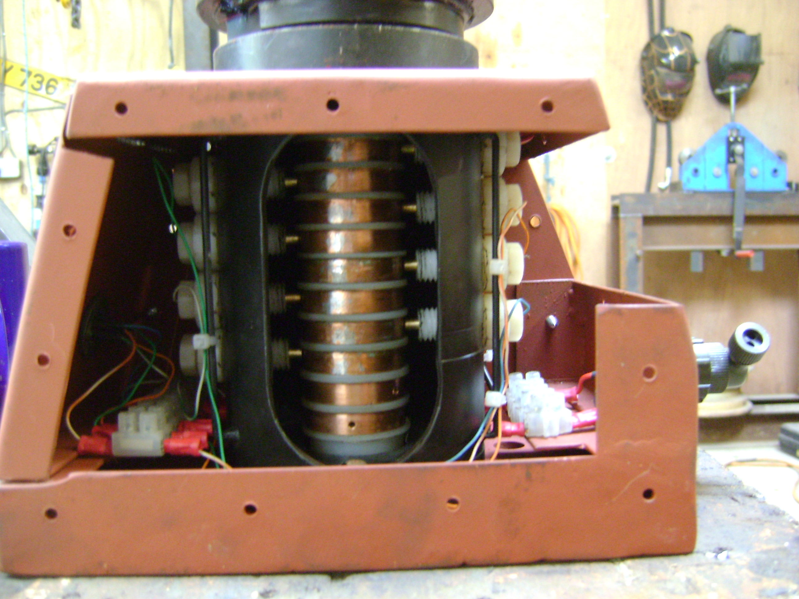
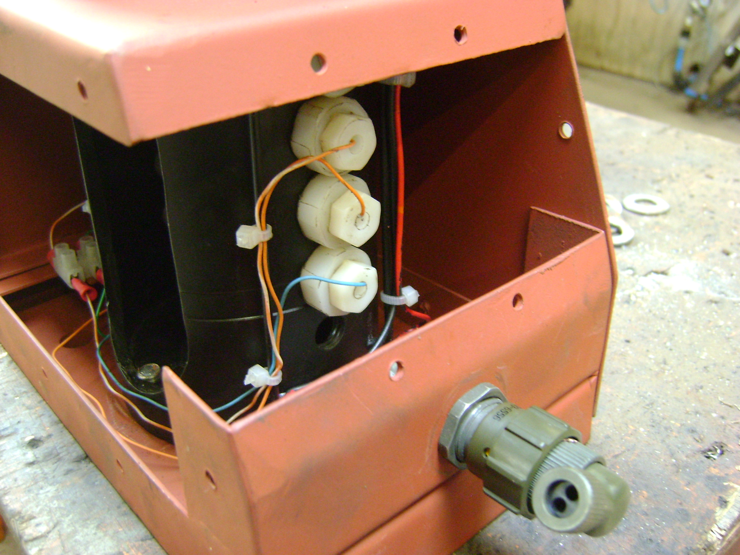
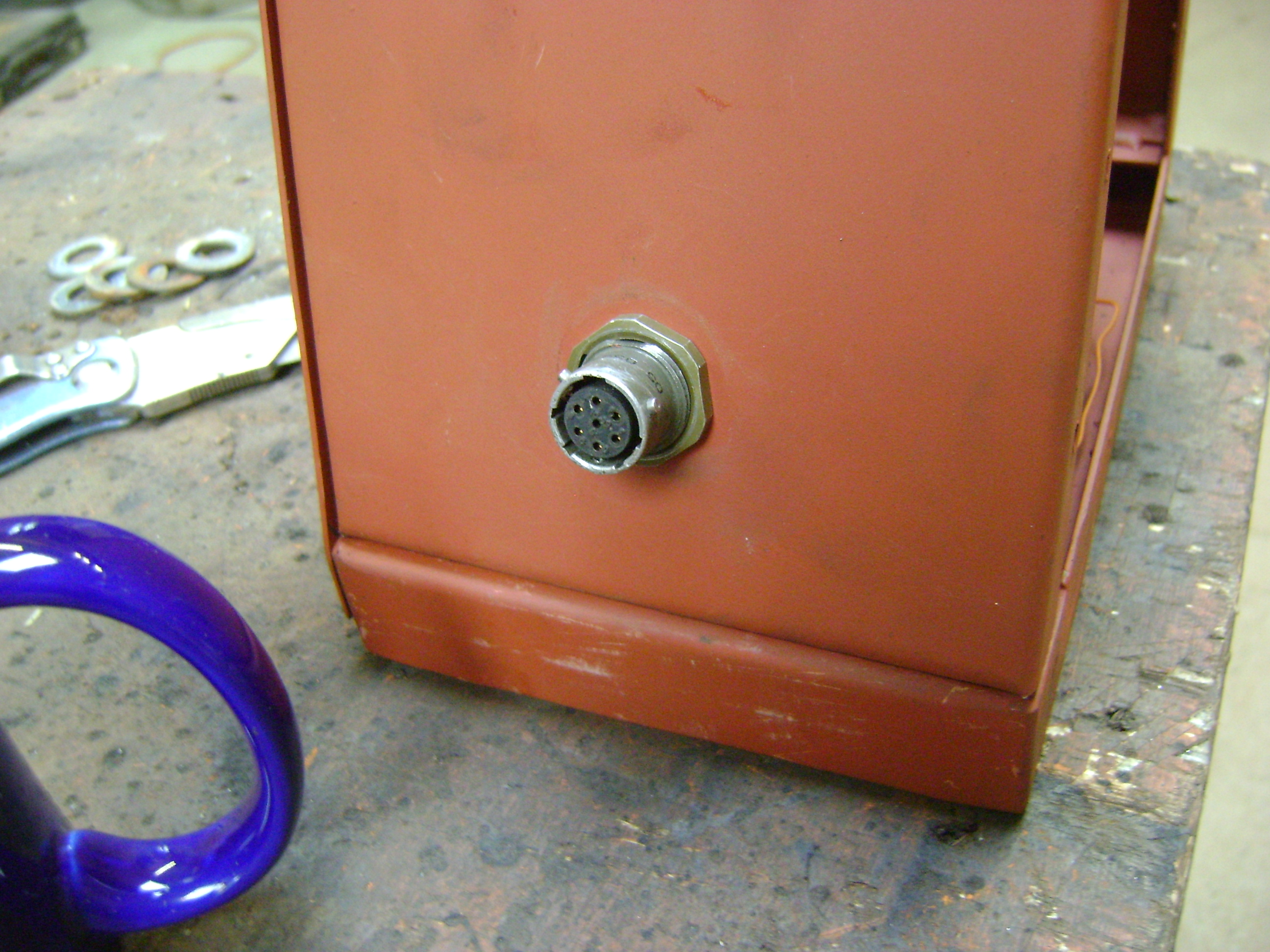
Evening all, Not much to report on the Panzer front, as I have been busy with other non military projects that I appear to have gained. As for the Panzer i have been removing the parts that i have previously made and under coating them ready for a top coat as and when. A quite interesting little project that i have finished is the rotary coupling that connects power and audio from the hull up into the turret. I had thought of using a cheap slip ring as sold on ebay and modifying it to suit but i don't think that it will be man enough, so i decided to knock something up myself. The rotary junction is bolted to the hull floor and attaches to the leg of the commanders seat, the cables then run inside of the seat support leg and into the turret. I thought that i had taken loads more pictures but it appears that i didn't. This is the rotor and the copper ring connectors, sorry if my descriptive terms are incorrect but i can't think what the individual components would be called. The copper is 35mm plumbing tube pressed over nylon insulators with the relevant wires soldered in. All the external connectors that i have used are clansman but i couldn't find a female socket, so i used a bulkhead fitting and turned up a two part housing that pushes together and sealed it all by covering it with heat shrink. The outer housing has a bearing top and bottom and an oil seal at the top to stop dirt getting in but i forgot to take a photo of the completed unit. The whole unit is housed in a fabricated steel enclosure that will be sealed with silicon on final assembly. Now a question for those who know more than I. Is there a recommended lubricant that i can use to stop corrosion of the copper, brass components, i was going to use vaseline or copper grease but neither are conductive and i fear that there will be a build up of any lubricant between the end of the probe and the copper ring that will cause problems. Any ideas? That's all for now. Jon


-
Hmvf has ceased to work on the traditional google browser, so i am now being forced to use chrome. Jon
-
Clear wax oil every time, then you can see what's happening under it. I have seen instances where black wax oil or other coloured products have been used, they look good but if they get chipped moisture gets under the coating and the material that you were trying to protect corrodes without you realising. Jon
-
Evening All, Update time again. I am still working my way around the track guards making all the various parts, boxes etc. On the right hand track guard, at the rear, there is a box described as a Werkzeugkasten III or toolbox, what exactly goes in it I have no idea. The box on top of the Wrkzeugkasten on the Tank museums Panzer II is an addition and isn't relevant to the Ausf C. Obviously mine. On the last update I mentioned the MG Zubehorkasten which caused some confusion. This is my recreation, which I think is somewhere near but how the items that it held were arranged, is still a mystery. The last item this evening, is what is described as Zwischenrohr zur Andrehkurbel or Intermediate tube to the crank handle. What the Intermediate tube to the crank handle actually looks like, I have no idea. An original on the tank museums PZII and mine. The catch used to close this tube and several other boxes caused me some head scratching. You can buy them from the good old USA at around $20 each, which to my mind is too expensive, especially as I need around 15 of them. They are not perfect but good enough. Or I could make them from scratch myself but I am too lazy. Then I came across these on that evil auction site. The dimensions are very similar to the original but of course they look totally different. With a little bit of imagination, some alteration and a new latch arm, I think that they look quite passable and all for £1.19 each. That's all folks. Jon


.png.3f42037ae465d14d70f35f3a1bc5c70c.png)

.thumb.JPG.3d5368a7fe88f2c885abb7fb4021e930.JPG)
-
.thumb.png.4854fbb26292d396a6b90659a3d1c4e2.png) As above, too many questions and I don't see the relevance. Jon
As above, too many questions and I don't see the relevance. Jon -
Evening and thanks for the information, I realise now that I should have been a bit more specific in my comments. You are correct there are several different Zubehorkasten but there is one that is specific to the Panzer ll, the nearest that I can find is the One from the Tiger tank pictured below but the dimensions are wrong. In this box the gun butt is stored on top of the bipod, thus the box is approximately 150mm wide, (because that is the dimension across the horns of the butt) by 380mm(the length of the bipod) by 80, the length of the removeable sight. The box that I seek has approximate dimensions of 440mm x 250mm x 60mm so the storage arrangements inside the box, must be different. I have the same problem with the MG Werkzeugtasche and the 2cm kwk Zubehorkasten that are stored inside the tank. The standard German armoured fighting vehicle had a steel MG Werkzeug But the early Panzers appear to have had a leather MG Werkzeugtasche as pictured above and in this Panzer 3 Now it has been suggested that these pictures are only storage pictures and the actual vehicle had either a steel box or the standard MG34 gunners pouch In fact if you study the pictures of the inside of the tank museums Panzer ll you can see the fixing points for the said pouch and the spacings are too far apart for either the standard gunners pouch or the steel box. Then there's the 2cmKwk Zubehorkasten, I have searched and I cannot find any information that relates to this particular box, I can find 2cm Zubehorkasten boxes but not that would fit and looking at the pictures of the angled brackets and what look like wood screws, I would think that this box could be made of wood. I could be wrong and if anyone has more information then I would be happy to receive it, the next step is to get down to Bovington and see what is in the archive but when? Jon


.jpg.b8bc82854b769c85d3892663bcf3eb03.jpg)


.jpg.28884b81bee80bf6e922bac845211199.jpg)


.jpg.3fa75ffde04ad3fd3f53dea18cbc1e56.jpg)
-
Evening All, One thing that I never throw away is Oak, I can always find a use for it. The panzer needs a jacking block as part of it's tool kit and as I had some large off cuts left over from when I built our extension, out came the chain saw. Most of the original blocks that I have seen have been made from several pieces joined together but I decided to make it out of one lump. The block in its holding bracket. I decided to use a new fire extinguisher painted to recreate an original, my thinking is, if there is a fire it would be nice to know that i have the equipment to put it out rather than to look good. The two other items that I have also have added are, the pinch bar and this enclosure that holds a box listed as an Zubehorkasten MG34, so far, i have been unable to find any information on the latter. Night, night, Jon


-
You could be right, maybe worth thinking about in the future. Evening All, I want to get all the tools, boxes, etc that are attached to the track guards in place before I remove the upper hull, all of the tools are held in place by these clips, An original My version I had thought that they would all be the same and I would just have to make 8 identical clips but in true German fashion, nothings that simple. There are 7 different variations to make, some just bigger or small but others totally different so each one takes a bit of experimentation. They were all lined with felt or similar, so that has to taken into account and that will be riveted in place after they have had a coat of under coat. That's all for now Jon


-
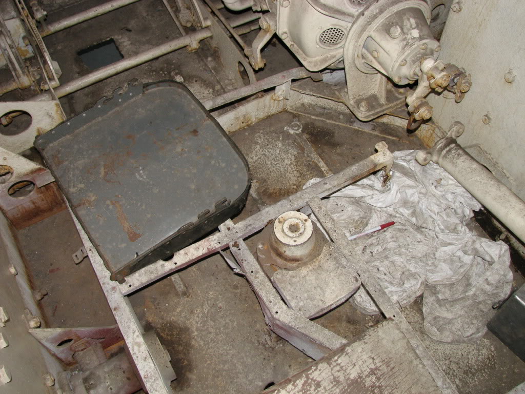
Thanks Tapper, it feels very close and yet there are still several major hurdles to negotiate but that's all part of the challenge. Time for an update me thinks. I have finished the engine cover although I have cheated and used 1.6mm steel sheet for the covers to save weight. Around the opening of this cover there is a radiused section, best shown in this picture. Also there is a 15mm gap right around the covers, too big a gap to be just clearance. I had assumed that it was a rain water channel but the more I studied the pictures I realised that the reason for the large gap and the radiused section was to allow air into the engine bay around the sides of the covers but I assume, not allow splinters to enter. On the original tank the two covers were not locked together, the lower over had no locking mechanism being held in place by it's own weight and the top cover having a locking mechanism. In my tank the covers lock together, as the lower door is not heavy enough stay in place on it's own. The radio operators escape hatch mow has it's latch and handle. Next to the radio operators chair there is a wall which is part of the engine bay bulkhead which for some reason is cut across at about 45 degrees Most probably to give access to the engine bay from inside the tank. Most of the pictures that I can find show this as being a bolted in section apart from one that shows it as having a hinged access door. I decided that as my ignition coil and amplifier are situated in this area a hinged cover would be a very good idea. When I made the radiator hinged cover, I made it as a two piece assembly. Once the hull top was in place it became obvious that it wouldn't close and should have been made in three sections. The only thing that then concerned me, was would it block the radio operators escape hatch. Once I had altered it, it became obvious that it tucks away nicely out of the way. The radio aerial on the panzer 2 is raised from inside the tank using this device. The handle is rotated up to raise that aerial and rotated down to lower it. The end of the handle is sprung so that when it is in the raised position it locks it's self in position, to lower the aerial you pull the end of the handle out and rotate it down. The unit to the right of the main unit contained a rotary coupling for the cable from the aerial to the radio apparatus. The shaft going between the rotating unit and the aerial outside the tank would have been in two parts and insulated so that the operator didn't get a shock when he touch the handle. In mine the shaft is in one piece. The radio mast was attached to the shaft via a coupling. This is the one on the Panzer ii in Bovington. And mine. When the mast is in the down position, it lays in a wooded tray that is bolted to the track guard. Sorry that it was such a long update, I get carried away or as my darling wife says, I should be carried away. Jon


_LI.thumb.jpg.394233143819615e52c831c4b8b92a00.jpg)


_LI.jpg.fa0d8b678841c420b0bda225d9aef3a5.jpg)
- 661 replies
-
- 10
-

-

-
Email sent Jon
-
Thanks again for the comments, they are all very encouraging, especially during the periods where enthusiasm is lacking. I always try to finish my projects as though they have just left the factory and then allow them age with use, which I don't think will take long with the tank, bearing in mind that you have to climb all over it to get in and out. Talking of which, climbing in and out to work on the interior plays havoc with the knees, I will be glad to get the upper hull off again and sit it on it's stand to finish things off. Not much to report as I have been getting on with some other projects but I have managed to make the engine compartment hinges and the lifting hooks and the rest of the resin was delivered on Friday, so back to casting next week. Jon


-
Evening All, Sorry John if it were easy I would put it on just for you but I am afraid that you will have to wait. The upper hull has had it's attachment flanges added and the whole structure has been bolted to the lower hull. I have manufactured and welded the track guard brackets to the upper hull, so now the tract guards are secure. Most of the rear engine deck has been completed but it needs removing to finish welding the inside edges. The cover on the left covers the radiator and air exhaust tract. I have had to add a hole that wasn't on the original in order to access the fan belt tensioner. The large access panel below that, gives access to the fan and the fan belt tensioner locking nut. This cover also houses the radio operators escape hatch, which itself is part of the cooling system and contains a fresh air inlet for the radiator. The cover seemed to take ages, as I had to work out what the hinges looked like and how they worked, so that they gave clearances for opening. The radio operators means of escape is very tight, as you can see. The cover to the right covers the engine bay. I was worried about access to the engine but although tight, everything seems fairly accessible. In the righthand side of this cover there are air vents that allow the fan to draw air over the engine. The air is the drawn through the fan and exhausted out of the rear of this same cover. And there endeth the lesson for today. Jon


.jpg.d42c075e9d64c9928ca7d4f7791080a3.jpg)
- 661 replies
-
- 10
-
-
-
Humber Heavy Utility for restoration Sale
johann morris replied to AmphibAndy's topic in Heads Up: For Sale!
A lovely vehicle and something that I would really enjoy restoring but way over priced for it's condition. I can just imagine the conversation with my dear wife. Jon -
That really does look the dogs dangly bits! Jon
-
Yes, I only spray with it and it gives a nice finish. Jon
-
I use a polyurethane matt, which is in actual fact slightly satin and very hard wearing. The company mix which ever colour you want and it's £57 for 5 litres. https://tools-paint.com/7-511-polyurethane-matt-topcoat-5-litre-18765-p.asp jon
-
Evening All, Six road wheels finished and now I have to wait for more polyurethane. This is the new Panzer ll sports model. Today we pushed the hull outside to give the track guards a coat of under coat and to put the upper hull in place so that I can start to construct the engine deck. Someone asked me how I had made the turret ring, well this was my design. A series of bearings spaced around the turret ring circumference, eight vertical and eight horizontal bearings trapped between an upper and lower flange, so that the turret can't come off. When I described what I had manufactured, I was told that it was the same as on an American Stuart light tank but as I have never seen a Stuarts turret ring, I can't comment. Jon


-
Plan John, did someone mention a plan, I thought I made it up as I went along. In truth the tracks are the one unknown. I could try to find enough originals or have some cast or even fabricate them, cost is a huge factor. So now you know as much as I do and that's not a lot, lets wait and see what turns up. Jon
-
Thanks for the comments It was obvious from early on, that the retaining clips that go around the exterior of the mould weren't going to give a very long life, so after casting the second tyre I decided to make a modification. It's a much better solution. My wood workshop has now become a casting shop for the duration and one of the other water tanks has become a make shift oven for drying the wheels after washing. Jon


-
Afternoon Again, Several years ago I bought a small shot blast cabinet but as my projects get bigger, I have out grown it. I have been looking at larger commercial cabinets but they seem very expensive for a box, so I thought that I would make one. When we bought the house there were several galvanised water tanks around the land which I was tempted to scrap but instead, I shoved them in a hedge for safe keeping. The larger one is an ideal size, the shot media reservoir is an old bucket welded underneath and the door some 3/4 ply that was left over from another project. I bought the gloves but made the arm hole surrounds from some odd bits of steel. It's all a bit bodge it and scarper but it works really well. Jon


-
Afternoon All, First road wheel out of the mould. Jon


.thumb.png.4854fbb26292d396a6b90659a3d1c4e2.png)
.jpg.ec33412927cd557dcfc87082f50da6fb.jpg)


.png.3f42037ae465d14d70f35f3a1bc5c70c.png)

.JPG.a82ce18931047101253c71b96b9cf6e0.JPG)


.jpg.b8bc82854b769c85d3892663bcf3eb03.jpg)


.jpg.28884b81bee80bf6e922bac845211199.jpg)


.jpg.3fa75ffde04ad3fd3f53dea18cbc1e56.jpg)


_LI.jpg.967fdbf806473264d1aea97c84ecd7d4.jpg)


_LI.jpg.fa0d8b678841c420b0bda225d9aef3a5.jpg)


.jpg.d42c075e9d64c9928ca7d4f7791080a3.jpg)


